Just noticed one of my answers on StackOverflow got some attention—well okay, one vote, but it’s better than zero. I’m not sure how relevant it still is given how fast ClojureScript seems to move, but I did include the code for my benchmarks, so hopefully at least that is still useful.
Entity Component System
About a year ago, I was listening to a talk by Chris Granger on how he leveraged the Entity Component System (ECS) architectural pattern when building LightTable. I’d never heard of the pattern before, probably because it typically finds its use in video games, and I don’t really do anything in the way of video game development. Chris did a pretty good job selling the approach, so I decided to try it for myself. A couple of months ago, I started working on an Asteroids-like game as a side project to evaluate this pattern, my particular interest being its effectiveness at facilitating code reuse, decoupling, and testing. It’s not done, but I’m sufficiently far enough along to get a sense of how the pattern plays out in practice. I won’t go over what the ECS is (check out Chris’s talk or the Wikipedia article if you’re interested in that), but instead just give a brief evaluation of its effectiveness.
Code Reuse
This does turn out to be a real win. By simply adding a new property to an entity, I can endow it with new behavior. For example, by giving the camera entity a movement component, I can make it so that it rotates or scrolls. I can also make the ship explode in the same manner as the asteroids by giving it an asteroid-explosive-death component. This means that once I add a new set of components and systems, I can take advantage of them on any entity that I’d like. Definitely a big win for code reuse!
Decoupling
The story here is a bit more mixed. On the one hand, the different systems do not directly call each other, and this leads some people to conclude that they aren’t coupled, but lets take a look at that. Here’s the function that takes a world at time t1 and generates a world at time t2:
1 2 3 4 5 6 7 8 9 10 11 12 13 14 15 16 | |
In general, it looks pretty simple. Each system takes a world state as a parameter and produces a world state as its value. Then the ability to move a game state forward is realized by composing the various systems together. It’s in that composing bit where the complexity hides: the order in which the systems are composed together matters! For example, the impulse-damage-system must be applied after the collision-physics-system as the former is looking for entities with an impulse component which is added by the collision-physics-system. One cannot simply look at the systems in isolation, but must have an awareness of how the systems interact with each other, which increases the cognitive load when adding, modifying, or removing systems. On the plus side, the systems are at least loosely coupled as they just care about the world being in some state, not about who put it in that state.
Of course, one could argue that this complexity is inherent in the problem (i.e. there’s just no avoiding it), or not a failing of entity component system, but rather an issue with the way I applied that pattern. The important thing here is to keep in mind that the lack of a direct function call doesn’t necessarily mean two parts of a system are decoupled, and it’s valuable to identify these areas of complexity because they help you understand where the problems are going to arise.
Testability
This turned out to be a huge win. Since none of the systems call each other, each system only cares about the world state passed into it, and none of them (at least none of the ones listed above) have any side effects, testing is a breeze! Here’s what one of my unit tests for the physics-system looks like:
1 2 3 4 5 6 7 8 9 10 11 12 13 14 15 16 17 18 19 20 21 22 23 24 25 26 | |
Notice how there aren’t any mocks. I just build a world state, call the system, and verify that the new world state looks the way it should. I wish that everything I did was this straight forward to test!
Conclusion
In general, I found that entity component system, as an architectural pattern, really shined in regards to code reuse and testability. I did not find the different systems as insulated from each other as I originally expected, but nonetheless, the complexity is manageable, especially with how easy testing is. My next step—other than actually finishing the game—is to investigate its viability in contexts outside of game development. LightTable just recently became open source, and since Chris Granger’s talk on how he used this pattern in LightTable got me interested in the first place, I’ll probably start there by analyzing its source code.
Building a Quadrature Rotary Encoder
Today I document the saga of building an quadrature rotary encoder. I undertook the project as a way to become more familiar with electronics. My more optimistic past self thought the task relatively straight forward, but a few months of misteps, redsigns, and code rewrites have taught me otherwise. Nonetheless, it’s been quite a learning experience, and hopefully this post will provide some guidance to anyone taking on a similar project.
Basics of a Quadrature Rotary Encoder
A quadrature encoder translates rotational changes of an object into a digital signal. They have a number applications, including robotics where they are used to determine velocity and position which can be infered from the rotation of the motor shaft(s). There are a number of ways to do this, but the ways I’ve experimented with involve an encoder wheel (Figure 1), and the use of infared emitters and collectors. To keep it simple for now, lets consider only one emitter and one collector. The encoder wheel is designed to alternate the amount of infared light reaching the collector from low to high at regular intervals as it rotates. One can acheive this by either “cutting out” the black sections in Figure 1 and placing the collector on one side of the disc and the emitter on the other such that as the disc rotates it will block and unblock the collector. The other method involves taking advantage of how light colors reflect more infared light than dark colors. Thus by placing the emitter and collector on the colored side of the encoder wheel, the same effect can be achieved as the amount of infared reflected will vary from low to high, and consequently the amount reaching the collector will vary from low to high, as the encoder wheel turns. In both cases, the analog output of the collector will look something like Figure 2 which is then turned into a digital signal also show in Figure 2.


From this signal, one can determine speed based upon the frequency—the higher the frequency, the higher the speed. Unfortunately, this signal doesn’t provide one critical piece of information: the direction.

By adding a second emitter/collector pair, radially aligned with the first pair, and adding a second encoder track to the encoder wheel offset by one quarter cycle as in Figure 1, the signal generated by both collectors will provide the direction. Call the outer track channel A and the inner track channel B, the collectors will produce a signal like in Figure 3, known as a quadrature signal, when the encoder wheel is rotating. For any point in time, these two square waves fall into 4 possible states, which can be represented by two digit binary codes called gray codes:
- channel A high and channel B high (11)
- channel A high and channel B low (10)
- channel A low and channel B high (01)
- channel A low and channel B low (00)
When the wheel turns clockwise, it produces the sequence of gray codes: 00, 01, 11, 10, 00, 01, etc. When turned counterclockwise, it produces the same sequence but in the opposite order: 00, 10, 11, 01, 00, 10, etc. Thus the direction of rotation can be inferred from the order of the gray codes. That’s the basics of an quadrature rotary encoder.
What I’m looking for
I have a somewhat larger robotics project I’ve been considering working on (I won’t talk about the specifics until I start on it), and this encoder fits into that larger scope. In this larger project, I’m considering using a scooter motor and wheels for locomotion, and I want to build a pair of encoders to get rotational information from the scooter wheels which I can then use to determine velocity and position. The encoders will also tie into a Kangaroo motion controller, which will in turn drive a Sabertooth motor controller. For the most part, the standard quadrature output covers my basic needs; however, I have a few other features in mind such as being able to calibrate the encoders programmatically, perform error checking and error notification, and also provide some basic encoder state information via an I2C interface.
Trial and Error
Attempt 1 – Photo Interrupter
For my first attempt, I thought I’d keep things simple, and then build upon it later once I got something working. I decided to use a disruption technique by which the encoder wheel would disrupt infared transmission from an emitter to a collector as it turned, as opposed to some sort of infared reflection approach. In the spirit of keeping things simple, I built a single channel encoder wheel out of a paper plate by cutting 180 prongs/teeth out of it. I attached it to the sproket of the scooter wheel I was building the encoder for using rare earth magnets (of course, I intended to come up with a more robust solution later). With 180 teeth in the encoder wheel, I could achieve (or thought at least) a resolution of 180 pulses per revolution, which seemed conservative as encoders with over 5 times the resolution are both relatively common and cheap (e.g. this encoder on SparkFun). For the infared emitter/collector, I purchased a GP1A57HRJ00F photo interrupter from SparkFun. What made this photo interrupter ideal was that it already had the infared emitter and collector aligned with a perfect slot for the encoder wheel to pass through. It also produced a simple digital output, no analog jazz to worry about. I utilized an Arduino Uno to process the quadrature signal by polling a digital pin connected to the output of the IR collector. It simply wrote to the serial device whenever a revolution was completed.
The first issue I ran into was cutting out the teeth in the encoder wheel. I didn’t really have a great solution for this, and ended up spending a couple mind numbing hours cutting out the individual teeth one at a time. I should have just printed the encoder wheel on a transparency, which would have obviated the need to cut any teeth out at all.
Aside from the time consuming annoyance of the encoder wheel, there was also the little issue of the encoder flat out not working at all. The number of pulses recorded per revolution undercut the expected 180 by as much as 20 pulses. To make matters worse, the results were not consistent. I concluded that some of the teeth on the encoder wheel were too thin to properly block the IR. I tried reworking the wheel a few times but the results didn’t get much better. In retrospect, what I originally saw as a benifit of the GP1A57HRJ00F photo interrupter was probably a draw back as it’s digital output denied me the abiliy to adjust the collectors threshold as to what denotes an ON state versus an OFF state. I could have also addressed this issue by reducing resolution (putting fewer teeth in the encoder wheel) but I was still too naive to sacrifce resolution for the sake of getting something that at least functioned.
Attempt 2 – IR Reflection
After spending the better part of a month trying to get the disruption approach to work, I decided to switch gears and use IR reflection instead. I purchased a SEN-00241 IR emitter and collector pair to use for the sensor. I went with a single channel once again just to try and get something working. Instead of creating an encoder wheel to mount on a scooter wheel, I simply printed one out, punched a hole through it, and attached it to a pencil. I then built a relatively stable mount for it out of an old Saltine Crackers box. At this point, I just wanted to see some positive results before I went to the trouble of making something more permanent.
I used the Arduino Uno in much the same way as I did previously, except now it was reading an analog input coming from the IR collector. I set up a calibration routine where I’d rotate the wheel and then it would compute the average value from the analog input and use that as the threshold between the ON and OFF states. It would then continuoulsy poll the analog input to detect state transitions.
The main issue with relying on IR reflection is that it varies not only with the color of the surface but also the distance of that surface from the emitter/collector—the further the surface is away, the less IR light makes it back to the collector. Indeed, IR sensors like this are frequently used as proximity sensors. Consequently, in order to detect light and dark surfaces properly, the distance from the surface must be held constant. Unfortunately, the cut up paper plates I’d been using tend to warp, meaning the encoder wheel’s distance from the IR emitter/collector varies as it turns. Of course, I could have switched to a more robust material, but then I got an idea that would make such uneccessary.
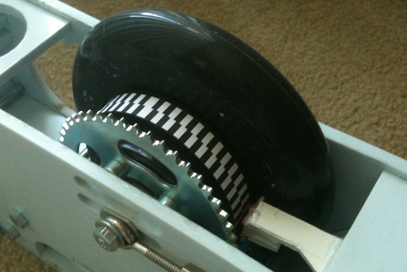
Attempt 3 – Encoder Strip and Sprocket Flange
After spending more time than I care to remember fighting with encoder wheels, I realized that I didn’t really need one. The scooter wheel I’m using connects to a sprocket using a flange and that flange happens to be just wide enough for an encoder strip (Figure 4). I wrote a small Groovy script to generate the encoder strip, printed it on standard printer paper, cut it out, and then glued it with some Elmer’s stick glue to the flange. Again, I started with a single channel, and I used the same SEN-00241 IR emitter/collector pair as before. The initial results were promising. I could acurately determine when the wheel had completed a revolution (so long as I didn’t change the direction of rotation).
With this initial success, I added a second channel to the encoder strip and purchased a pair of QRE1113 Line Sensor Breakouts from SparkFun. The main advantage of these sensor breakouts is that I can use a single 6-pin header to hold both sensors keeping them perfectly aligned with each other. I updated my code to calibrate both sensors and then to poll continuously both analog inputs. I also made it print out the current gray code as the wheel rotate. Briefly experimenting with it, everything seemed fine, but then I decided to do something crazy and add error checking.
Not all sequences of gray codes are valid. For example, you can’t go from 10 to 01 or 11 to 00. When an invalid transition happens, it usually means something not good just occurred. It could be that the encoder wheel is turning too fast for the encoder to keep up, the encoder strip/wheel might be damaged, the IR sensors could be out of alignment, or something of that sort. The error checking I added detected these erroneous transitions which it found with great frequency, especially when the wheel rotated at higher speeds. Even after reducing the resolution from 184 pulses per revolution to 92, the issue persisted.
My first guess as to the source of the problem was that, as I spun the wheel faster, the vibrations caused the distance to fluctuate between the IR sensors and the encoder strip, so I built a more stable mount for the IR sensors (alright, I used foamboard and a hot glue gun, but that should have been stable enough given my setup). This had no impact on the encoders performance.
I then decided it must be noise issues with the analog signal (at the time, I didn’t have an oscilliscope), so I updated my code to use a moving average filter. Again, nothing, in fact, the moving average filter seemed to do more harm than good. I also tried a median filter that also didn’t help, but didn’t seem to make things worse either.
Okay, not noise, not vibrations, what else? Well, the Arduino likes to take its time when performing analog reads. I calculated that at the faster speeds I spun the scooter wheel at, it could only manage 10 or so analog reads per encoder state. Given that the IR sensors were likely slightly misaligned, and the calibration of the sensors probably fell a bit short of optimal, the frequency at which the analog inputs were sampled may simply not have been high enough to catch every state transition. However, I would have expected decreasing the resolution to help more than it did. Another potential issue is that the Arduino needs to charge an internal capicitor when performing an analog read, which can be problematic if there isn’t sufficent current on the inputs to charge the capacitor in a reasonable amount of time, though I didn’t really look into this much.
There are a number of ways I could have dealt with the poor analog read performance. I could have bypassed Arduino’s analogRead(..) function and its overhead. I could have sacrificed analog read percision to increase the sampling rate. I could have fixed any alignment issues with the IR sensors. I could have done all those things, but I decided there was a better way to go about getting state information from the sensors.
Attempt 4 – Encoder Strip with Interrupts
Since detecting state transitions by polling didn’t work, I decided to go the interrupt route instead. I avoided using interrupts up to this point mainly due to their rather negative impact on code complexity. Dealing with the flow of execution getting yanked away at any point, and ensuring the interrupt handlers and main loop don’t read or write global data in an inconsistent manner, is hard to manage in an elegant and simple way.
I purchased some Microchip MCP42010 digital potentiometers and TI LM339N voltage comparators from DigiKey. The analog signals from the IR sensors were fed through the voltage comparators and their output went to an interrupt on the Arduino. The digital potentiometers were used to create the reference voltage for the voltage comparators and were appropriately programmed during calibration. There were also some extensive code changes as well which I won’t go into here.
This approach generated immediate positive results. I currently have the encoder operating with a resolution of 180 pulses per revolution with no issues. There are still a number software problems to work out, and hardware wise, I still need to make a ciruit board, but the main obsticales to progress have finally been overcome.
Next Steps
Now that I have a working circuit, I need to start looking into how to turn that circuit into a circuit board. Luckily, my friend Andy recently showed me how to go about making a circuit board using a DIY photoresist method which, at least when he does it, produces some rather impressive results with a relatively low time/money investment.
Migrating From WordPress.com to WordPress.org
Recently at meltmedia, I had to port a blog for one of our clients from WordPress.com to a self-hosted WordPress.org install. Normally, most of the work I do is with Java, JBoss, OSGi and technologies of that sort, so working with WordPress and PHP was quite a new experience for me. At first, the thought of porting a WordPress.com blog to a self-hosted WordPress.org solution seemed like a simple matter, but it ended up being more involved than I expected.
Our client used a number WordPress.com features not available in a vanilla WordPress.org install, namely: social network sharing for posts, publicizing tools for Twitter and Facebook (among others), slideshows, email subscriptions, site stats, short links, embedded video shortcodes, a Twitter feed widget, and special support for mobile clients. WordPress.com provides some of these features through equivalent plugins for WordPress.org, others are just 3rd party plugins, and some are proprietary with no directly equivalent WordPress.org counterpart.
I originally installed the Sharedaddy, WordPress.com Stats, and Wickett Twitter Widget plugins to provide the social networking for posts, stats, and twitter widget functionality respectively, but later on switched to using WordPress.com’s Jetpack plugin (released while I was working on the port) which provides the same features as well as shortcodes for embedded videos and short links. Jetpack proves satisfactory in most respects, though it does have the drawback of requiring a WordPress.com account (not a big deal since the client already had one) and the plugin also requires that any WordPress.org instance using it be on a publicly accessible domain, which is problematic for development where I prefer to work (as I assume most developers do) on my localhost. Unfortunately, while JetPack does fill a number of gaps, there are still some proprietary features of WordPress.com for which it does not provide support, slideshows in particular.
WordPress.com has this nice feature where if you put a [slideshow] shortcode in a post’s content, it will be replaced by an animated slideshow of the images attached to the post. To my knowledge, WordPress.com provides no plugin for this feature, though they stated in a blog post from over a year ago that such a plugin would soon be available. Sadly, despite my best efforts, I could not find a suitable plugin to provide the same functionality. While there is certainly no shortage of slideshow plugins for WordPress.org, each of them seems to have one shortcoming or another. For example, NextGEN Gallery provides, among many other great features, support for in post slideshows, but it was incompatible with the WPtouch plugin that I also needed, and it doesn’t simply use the images attached to the post, but requires a set of images to be uploaded and grouped together separately from the post. Arguably, this latter issue is less of a shortcoming than a more appropriate and flexible way to manage the relavent data, but I wanted to make the change of hosts as transparent as possible to the client, and requiring them to manage such information elsewhere seemed too disruptive to their existing work flow. I also looked into Slideshow Gallery, and a number of its derivatives, but they had poor support for images of varying sizes and also proved similarly difficult to get working with the WPtouch plugin. In the end, I was unable to find a replacement for the slideshow feature, though I’m hoping a future version of Jetpack will include such support. I’ve been toying with the idea of creating my own replacement, the WordPress.com slideshow is essentially just a wrapper for the jQuery cycle plugin, but time being the rare commodity it is, I’ve yet to get around to it.
Email subscriptions is another area where no directly equivalent plugin exists. I ended up electing to use MailPress to fulfill this requirement, which is overkill for the task, user subscription for notification by email of new posts and comments on the site, but it works. Transferring existing subscriptions over proved relatively simple. A subscriber list CSV export can be acquired through the WordPress.com admin interface (it’s located, somewhat confusingly, in the stats section), and MailPress has a subscriber import tool which can import the data. The only issue was that MailPress didn’t like that the CSV file generated by WordPress.com had only a single column, but its complaints were silenced by simply adding a comma to the end of each line in the CSV.
The mobile optimized support that WordPress.com offers comes from the WPtouch Pro plugin that I eluded to earlier. Out of the box, it’s pretty much configured in the same way it is on WordPress.com, so it took little effort to get it working. I do have some issues with the plugin itself, but none relavent to someone who simply wants to port a blog from WordPress.com to a WordPress.org install.
Porting the data itself from WordPress.com to the new WordPress.org instance was for the most part painless. WordPress comes with a built in export tool that allows for the export of all post data (including custom post types) from a WordPress install, and this export can be easily imported into a WordPress.org install using the WordPress Importer plugin. However, there isn’t any mechanism to transfer theme, site, and plugin configuration from WordPress.com, so this ends up being a manual process filled with tedium and potential for error. I wrote a script to configure most of this for me during development, but there isn’t a good way, that I’m aware of, to automate the entire ordeal. To redirect users from the WordPress.com blog to the new WordPress.org instance, the client purchase WordPress.com’s site redirect upgrade. Unfortunately, it’s not free costing $12.00 per year, but it does work.
In the end, the blog migration from WordPress.com to a self-hosted WordPress.org site was a success, albeit not quite the smooth transition I’d hoped for. The only feature missed from WordPress.com was it’s slideshow support, but I imagine with some additional effort that issue could be addressed. For those looking into porting a WordPress.com blog themselves, here are the plugins I ended up using: Jetpack, MailPress, Akismet, WPtouch Pro, and Simple Twitter Connect with the STC – Publish add-on.